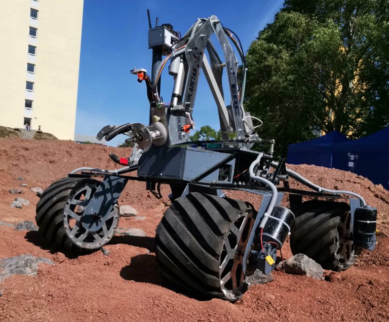
With the combined effort of all the team members and experiences gathered from past competitions, we have designed our rover Renaissance V2.0 for European Rover Challenge 2022.
This year the drive system consists of four wheels, each driven by a high torque planetary gear DC motors. These motors are independently controlled by separate BTS drivers. The motors are housed inside the wheel stator to protect it from external damage.
For the suspension system, we implemented a “Bar Differential Mechanism” with a counter-link at the front of the rover. This ensures that when the wheel on the right will go up, the wheel on the left will go down and the body will remain at an average angle between either way. So when the rover goes through rocky terrain, there will be minimum jerking of the body. This suspension system is more lightweight than the six-wheel rocker-bogie mechanism.
We have built a six-degree of freedom rover arm using stainless steel square tubes for better stability and precision. The base of the Rover Arm is located at the center of the body for proper distribution of mass and can rotate 360 degrees on its axis. A 100mm stroke Linear Actuator is used for shoulder movement whereas a 200mm stroke linear actuator is used for elbow movement. A two servo motors is implemented in the lower wrist to achieve precise pitch and yaw mechanism.
We have implemented DC Motor Mechanism in order to get the 360 degree roll motion of the end effector. A worm gear dual shaft DC motor with linear rails is used for the 2-claw gripper mechanism.
Our end effector can tighten a screw, undo a switch, turn a knob. We have attached a poly-fiber at the end of our gripper for better grip and stability.
We improved the strength of our 2-claw gripper system, with which we can pick up a container and transport it to another place, open and close a drawer and insert a cache into the drawer. The whole arm and manipulator is designed and built aligning with the Inverse Kinematics system that our software team is developing.
For the electric system we used four separate PCBs: Wheels, Arm, Science and Power. Each board is used for controlling and monitoring the respective sub-systems. All boards are equipped with Arduino Nano V3.0 for low level control. H bridge 43a BTS drivers and L289N drivers are used for driving the actuators and DC motors.
For the main computer we used a Nvidia Xavier NX. Intel RealSense D435i stereo camera along with a 9 DoF IMU is used for perception during autonomous navigation. ROS is used with a custom made interface for controlling the rover remotely.
The rover is equipped with a 13 dBi high gain Ubiquiti Airmax Omnidirectional antenna while the base station has a 15 dBi high gain Ubiquiti Airmax 120 degree Sector antenna. Both rover and base station uses Ubiquiti Aimax Rocket M2 routers. This communication setup allows us to control the rover for a No LOS (Line of Sight) distance of one and half kilometers.
For the soil collecting and probing mission, we have made robust changes to our soil collection module. By using scoopers, we collected surface samples and placed them inside specially designed containers to avoid contamination. Weight sensor (Load cell HX711) was used to measure weight of individual samples with 0.01g accuracy. Probes were collected using the rover arm and placed in a customized probe stand.
For science planning we had used CorelDRAW and Adobe illustrator to draw a geological map including the features of the provided mars yard. We also stated a hypothesis, related to the martian environment and later justified it in the scientific exploration part after field traversal. While traversing we also identified some interesting objects for the unplanned science report.